


 Language
 English
 русский
 Español
 Português
 Deutsch
 عربى
عربى italiano
 Türk
Türk हिंदी
हिंदी Indonesia
 Tiếng Việt
If you need any help, please feel free to contact us

Best Practices for Installing Ventilated Trough Cable Trays in High-Voltage Environments
Content
- 1 Thermal Management and Heat Dissipation Efficiency
- 2 Structural Integrity and Loading Requirements
- 3 Grounding and Electromagnetic Shielding
- 4 Installation and Spacing Optimization
- 5 FAQ
- 5.1 What is the primary advantage of a ventilated trough over a solid trough?
- 5.2 Which materials are best for outdoor high-voltage cable trays?
- 5.3 Does a ventilated trough tray provide protection against falling objects?
- 5.4 How does ventilation impact the EMI shielding effectiveness?
- 5.5 Can these trays be used for both power and data cables?
- 6 Technical References
In high-voltage electrical infrastructure, the management of thermal loads and electromagnetic interference is critical for system longevity. The ventilated trough cable tray represents a specialized hybrid solution, combining the physical protection of a solid-bottom trough with the heat dissipation capabilities of a perforated system. This technical analysis explores the engineering requirements for deploying these systems in demanding power distribution networks.
Thermal Management and Heat Dissipation Efficiency
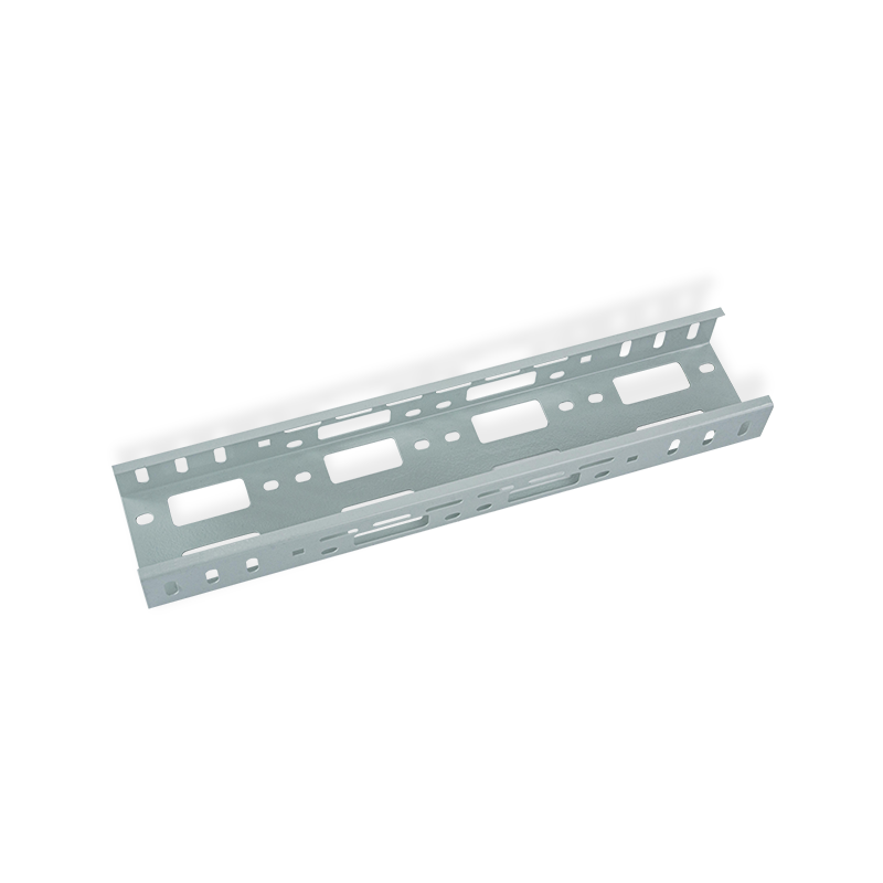
High-voltage cables generate significant ohmic heating during peak loads. Utilizing a ventilated trough cable tray design allows for consistent airflow around the cable jackets, which prevents insulation degradation. Unlike solid-bottom troughs, the ventilation slots facilitate natural convection, reducing the derating factor of the conductors. Engineers must calculate the free air area percentage to ensure it meets the specific ampacity requirements of the circuit.
When comparing different tray configurations for thermal performance, the ventilated trough offers a balanced profile between open-run ladders and fully enclosed troughs. The following data outlines the typical cooling efficiency across common cable management structures:
| Tray Type | Heat Dissipation Factor | Protection Level (Debris) |
| Solid Bottom Trough | Low | Excellent |
| Ventilated Trough Cable Tray | Medium-High | Good |
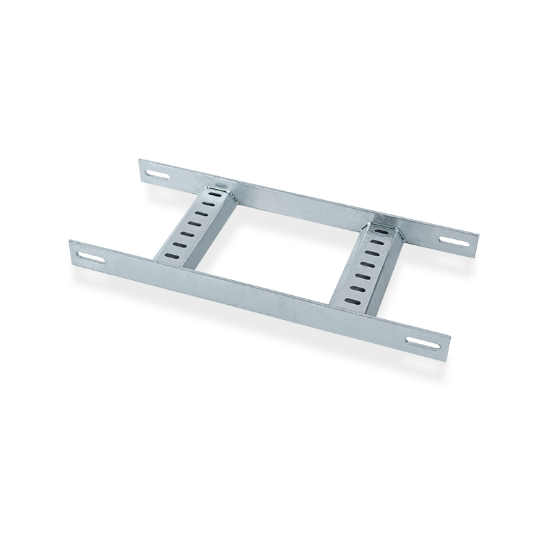
| Ladder Type Tray | High | Low |
Structural Integrity and Loading Requirements
The mechanical strength of a heavy duty ventilated trough cable tray is governed by the thickness of the base material and the geometry of the side rails. For high-voltage environments, the tray must support not only the weight of the cables but also potential short-circuit forces. Selecting aluminum alloy ventilated cable trays provides a lightweight yet corrosion-resistant alternative to steel, particularly in coastal or chemically aggressive atmospheres. Jiangsu Youming Group Co., Ltd., located in the Taidong Industrial Park, utilizes automatic forming and longitudinal shearing lines to ensure every section maintains precise dimensional tolerances and structural uniformity.
To determine the maximum allowable span, engineers refer to NEMA VE 1 or IEC 61537 standards. The ventilated trough cable tray load capacity is directly influenced by the support spacing and the thickness of the longitudinal side rails. It is essential to conduct a deflection analysis to ensure that the tray does not exceed 1/200 of the span under full load conditions.
- Material Selection: Stainless steel or hot-dip galvanized steel for maximum durability.
- Welding Standards: Utilization of automatic welding lines to ensure seam integrity and prevent stress corrosion cracking.
- Surface Treatment: Powder-coated or fireproof coatings for enhanced safety in substation environments.
Grounding and Electromagnetic Shielding
One common technical query is how to ground ventilated trough cable trays effectively. In high-voltage applications, the cable tray must act as an Equipment Grounding Conductor (EGC). Continuous electrical bonding across joints is mandatory, typically achieved through specialized splice plates and bonding jumpers. Furthermore, the ventilated trough cable tray vs ladder tray debate often centers on EMI shielding; the trough’s side walls provide a superior Faraday cage effect, reducing electromagnetic radiation from power cables that could interfere with sensitive communication lines.
Advanced Manufacturing and Quality Control
Precision in manufacturing is the foundation of site safety. Jiangsu Youming Group Co., Ltd. operates a 26,000 square meter production workshop equipped with CNC turret punching and laser cutting lines. As an ISO 9001:2015 and EU CE certified enterprise, the company integrates a dedicated testing center where raw materials and finished ventilated trough cable tray specifications undergo rigorous inspection. This ensures that every component, from the longitudinal shearing to the automatic spraying line, reaches a high industry level of 30,000 tons annual capacity.
Installation and Spacing Optimization
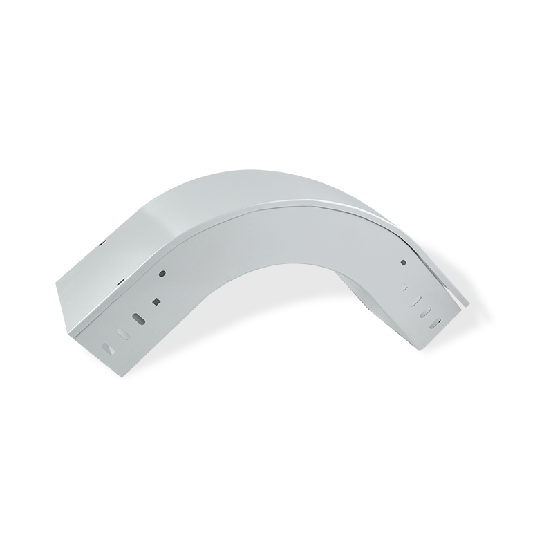
The ventilated trough cable tray installation guide for high-voltage systems emphasizes the importance of vertical and horizontal clearances. Proper ventilated trough cable tray spacing ensures that technicians can perform maintenance while maintaining safe approach distances. During the layout phase, engineers must account for the minimum bending radius of large-diameter high-voltage cables, ensuring the tray fittings (elbows, tees, and crosses) accommodate these radii without stressing the cable insulation.
| Installation Parameter | Standard Requirement | Engineering Objective |
| Minimum Clearance | 300mm - 600mm | Maintenance Access |
| Support Interval | 1.5m to 3.0m | Deflection Control |
| Grounding Resistance | Less than 1 Ohm | Personnel Safety |
FAQ
What is the primary advantage of a ventilated trough over a solid trough?
The primary advantage is improved air circulation, which allows for higher current carrying capacity (ampacity) of the cables by facilitating heat dissipation through the ventilation slots.
Which materials are best for outdoor high-voltage cable trays?
Hot-dip galvanized steel or 6000-series aluminum alloys are preferred due to their superior atmospheric corrosion resistance and structural load-bearing capabilities.
Does a ventilated trough tray provide protection against falling objects?
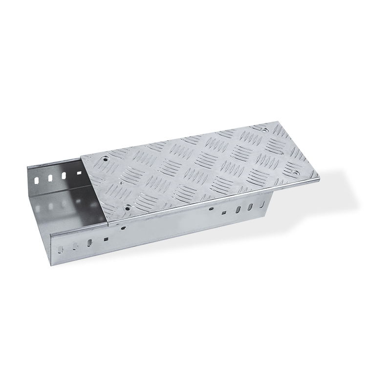
Yes, while it has ventilation slots, the trough structure provides significantly better protection for small falling debris compared to a ladder-type tray.
How does ventilation impact the EMI shielding effectiveness?
While the slots slightly reduce the total shielding compared to a solid trough, a ventilated trough still provides an effective electromagnetic barrier that is far superior to open ladder systems.
Can these trays be used for both power and data cables?
Yes, provided that a grounded metallic divider is installed to separate the power and communication cables to prevent signal interference and comply with safety codes.
Technical References
- IEC 61537: Cable management - Cable tray systems and cable ladder systems.
- NEMA VE 1-2017: Metal Cable Tray Systems.
- ISO 9001:2015 Quality Management System Standards.

Youming Group is a manufacturing group company mainly engaged in the research and development of new high-strength cable tray
Product
- Wire Type Cable Tray Series
- Punched Type Cable Tray Series
- Trough Type Cable Tray Series
- Cable Rack Ladder Series
- Ladder Type Cable Tray Series
- Marine Cable Ladder Tray
- Strut Channel Cable Tray Series
- Accessories
- Fiber Cable Tray/Optic Cable Tray
- Photovoltaic Stents
- Stainless Steel Cable Tray Series
- Aluminum Alloy Cable Tray System
Contact information
-
No.36, Taidong Industrial Zone Shiyan Town, Dongtai City, Jiangsu Province
