


 Language
 English
 русский
 Español
 Português
 Deutsch
 عربى
عربى italiano
 Türk
Türk हिंदी
हिंदी Indonesia
 Tiếng Việt
If you need any help, please feel free to contact us

Trough Cable Tray for Industrial Cable Management and Power Distribution Systems
Content
- 1 Trough Cable Tray Load Capacity: Understanding Support Spans and Ratings
- 2 Trough Cable Tray Corrosion Resistance: Coatings and Finishes Explained
- 3 Trough Cable Tray Installation: Support Spacing and Mounting Methods
- 4 Trough Cable Tray vs Ladder Cable Tray: Which One Fits Your Project?
- 5 Trough Cable Tray Material Options: Steel, Aluminum, and Fiberglass
- 6 Trough Cable Tray Applications: Where This Design Works Best
- 7 Frequently Asked Questions
A trough cable tray is a cable management system built with a solid or lightly ventilated bottom enclosed by continuous side rails, creating a channel that protects power and instrumentation cables from dust, debris, and accidental contact while still allowing heat to dissipate through ventilation slots. Compared to open ladder-style trays, the enclosed bottom of trough cable tray systems makes them the preferred choice for control cabling, instrumentation runs, and any application where cables need extra physical protection without the cost of full conduit.
Definition
Trough cable tray is a support system with a solid or lightly perforated bottom and continuous side rails, designed to carry and protect groups of cables along a fixed route.
Trough Cable Tray Load Capacity: Understanding Support Spans and Ratings
Load capacity for trough cable tray is expressed as a uniformly distributed load in pounds per linear foot, measured across a defined support span and tested to stay within an allowable deflection limit. Wider and deeper trays carry more cable but require closer support spacing to stay within that deflection limit, while narrower trays can often span further between supports. Specifying the right tray means adding up the weight of every cable that will ever run in that section, including spare capacity for future additions, and matching that total against the tray's rated load at the planned support spacing.
40-150 lb/ft Typical Load Range
6-12 ft Support Span Range
2-36 in Width Range
2-6 in Depth Range
Trough Cable Tray Corrosion Resistance: Coatings and Finishes Explained
Corrosion resistance in trough cable tray comes primarily from the finish applied to the steel, aluminum, or fiberglass base material. Pre-galvanized steel offers basic protection suited to indoor, low-corrosion environments, while hot-dip galvanizing after fabrication coats every surface, including cut edges and weld points, for outdoor and moderately corrosive settings. For chemical plants, wastewater facilities, and coastal installations, manufacturers offer stainless steel trays in 304 or 316 grade, or fiberglass-reinforced polyester trays, both of which resist saltwater, acids, and UV exposure without the periodic repainting that galvanized steel eventually needs.
Trough Cable Tray Installation: Support Spacing and Mounting Methods
Proper installation starts with support spacing, determined by the tray's load rating and the total weight of cable it will carry, typically ranging from 6 to 12 feet between supports for standard loads. Trapeze hangers, wall brackets, and ceiling-mounted threaded rod supports are the most common mounting methods, and expansion fittings should be added every 24 to 30 feet of straight run to accommodate thermal movement in outdoor installations. Bonding jumpers across each connection point maintain electrical continuity for grounding, which most electrical codes require regardless of the tray's finish or material.
Trough Cable Tray vs Ladder Cable Tray: Which One Fits Your Project?
Trough cable tray and ladder cable tray share the same rail and rung structure, but the solid or lightly perforated bottom of a trough tray changes how each performs in practice. The table below compares the two designs across the factors that matter most when specifying a tray.
| Attribute | Trough Cable Tray | Ladder Cable Tray |
| Cable Protection | Enclosed, shields from debris | Open, cables exposed |
| Heat Dissipation | Moderate, via ventilation slots | High, fully open rungs |
| Best Suited For | Instrumentation, control, fiber | Power feeders, large conductors |
| Fill Inspection | Limited, may require cover removal | Full visibility along the run |
| Typical Cost per Foot | Slightly higher | Generally lower |
Trough Cable Tray Material Options: Steel, Aluminum, and Fiberglass
Trough cable tray is manufactured in three primary materials, each suited to a different environment. Galvanized or painted carbon steel is the most economical option and covers the majority of indoor commercial and industrial installations. Aluminum trough cable tray weighs roughly half as much as steel of the same dimensions, resists corrosion without coatings, and is popular in food processing and pharmaceutical plants where frequent washdown is required. Fiberglass-reinforced plastic trough tray is non-conductive and chemically inert, making it the standard choice for chemical processing plants, water treatment facilities, and offshore platforms.
Trough Cable Tray Applications: Where This Design Works Best
The enclosed bottom of trough cable tray makes it the default choice anywhere cables need protection from physical damage or contamination without the expense of conduit, which is why it appears across such a wide range of facilities.
- Instrumentation and Control Wiring Process plants route low-voltage signal and control cables in trough tray to shield them from electrical noise and accidental contact with power cabling.
- Data Center and Telecom Cabling Fiber optic and structured cabling runs benefit from the smooth, enclosed channel that prevents sharp edges from damaging cable jackets.
- Commercial Building Risers Vertical cable risers between floors use trough tray to contain cable bundles while maintaining fire-rated separation between levels.
- Outdoor and Rooftop Runs Solid-bottom construction keeps debris, ice, and direct sun exposure away from cables routed across rooftops or between buildings.
Frequently Asked Questions
What load class should I choose for trough cable tray?
Match the rated load to the combined weight of every cable the tray will carry, plus a margin for future additions, then confirm that figure stays within the tray's rating at your planned support span. Most commercial installations fall within the 50 to 75 lb/ft range at a 10 to 12 foot span.
Does trough cable tray need a cover?
Covers are optional indoors in clean environments but recommended outdoors or anywhere debris, dust, or direct sunlight could reach the cables, since a cover protects cable jackets from UV degradation without affecting the tray's load rating.
Can trough cable tray carry both power and control cables?
Yes, but most electrical codes require a barrier strip or separate tray sections when power and control cables share the same tray, to prevent electromagnetic interference between high-voltage and low-voltage circuits.
How is trough cable tray grounded?
Bonding jumpers connect each tray section across joints and expansion fittings, and the entire run is tied to the facility grounding system at the intervals specified by the applicable electrical code.
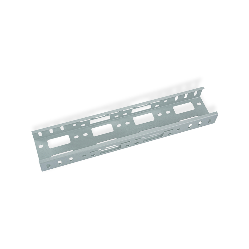
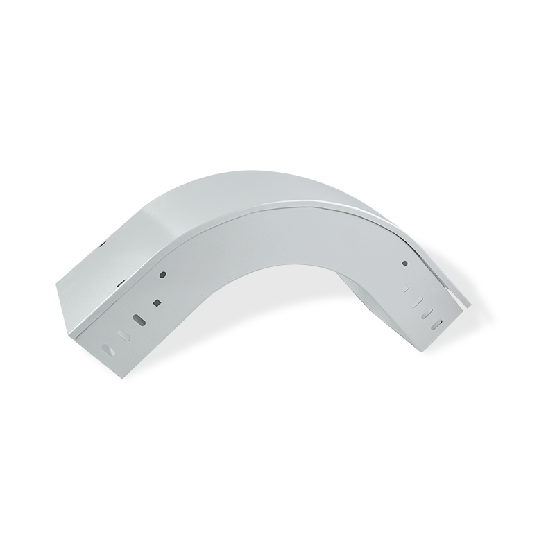
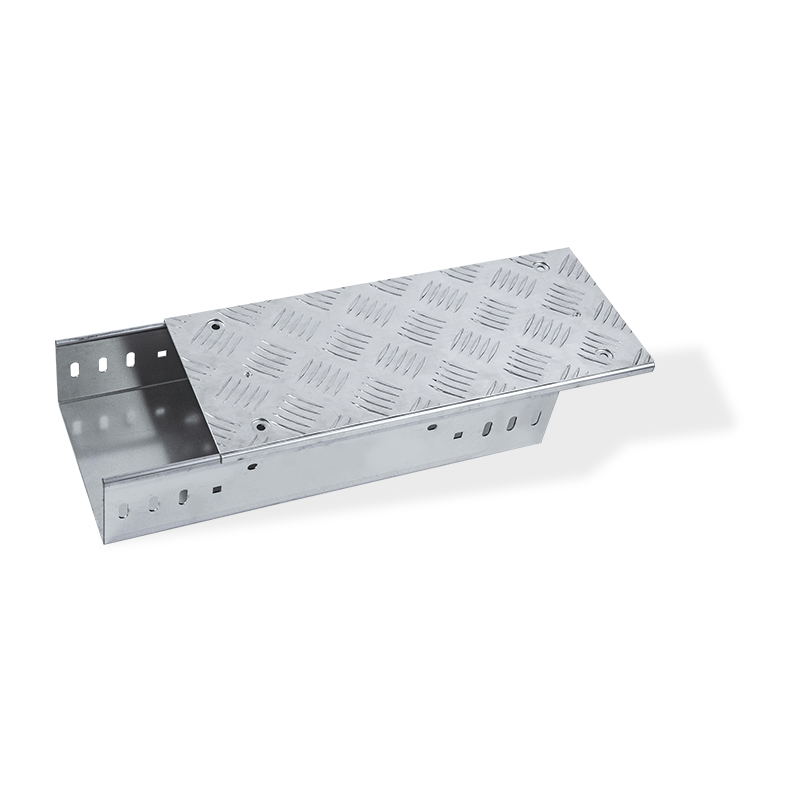
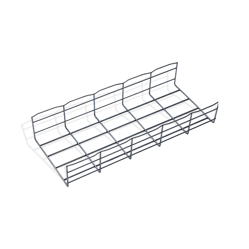

Youming Group is a manufacturing group company mainly engaged in the research and development of new high-strength cable tray
Product
- Wire Type Cable Tray Series
- Punched Type Cable Tray Series
- Trough Type Cable Tray Series
- Cable Rack Ladder Series
- Ladder Type Cable Tray Series
- Marine Cable Ladder Tray
- Strut Channel Cable Tray Series
- Accessories
- Fiber Cable Tray/Optic Cable Tray
- Photovoltaic Stents
- Stainless Steel Cable Tray Series
- Aluminum Alloy Cable Tray System
Contact information
-
No.36, Taidong Industrial Zone Shiyan Town, Dongtai City, Jiangsu Province
