


 Language
 English
 русский
 Español
 Português
 Deutsch
 عربى
عربى italiano
 Türk
Türk हिंदी
हिंदी Indonesia
 Tiếng Việt
If you need any help, please feel free to contact us

How to Choose Wire Basket Cable Tray for Efficient Cable Management Systems
Content
The wire basket cable tray has become the standard cable management solution across data centers, industrial plants, commercial buildings, and telecom infrastructure — valued for its open-mesh construction, ventilation, flexibility, and ease of installation. This guide provides electrical contractors, facility engineers, and procurement buyers with a structured technical reference for selecting, specifying, and deploying the right system for their application.
What Is a Wire Basket Cable Tray?
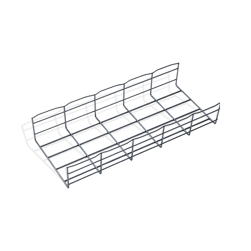
A wire basket cable tray is an open-structure cable support system formed from welded steel wire rods, shaped into a basket-like channel that routes and organizes power, data, and signal cables through buildings and facilities.
Core Definition
"A wire basket cable tray is a factory-welded wire mesh support channel that provides ventilated, flexible, and accessible cable routing for electrical, data, and telecom infrastructure — without the enclosed structure of conduit or the rigidity of solid-bottom ladder tray."
- Open mesh construction allows full airflow around cables
- Field-cuttable and bend-adjustable without special tooling
- Supports cable additions and rerouting without tray replacement
- Available in widths from 50 mm to 600 mm and depths from 35 mm to 150 mm
- Compliant with IEC 61537 and equivalent national standards
How Wire Basket Cable Tray Differs from Ladder and Solid-Bottom Tray
Ladder trays use solid side rails with widely-spaced rungs — better suited to large, heavy power cables over long spans. Solid-bottom trays provide full mechanical protection but restrict airflow. The wire basket cable tray occupies a practical middle ground: it supports medium to high cable densities with full ventilation, accepts frequent cable changes, and installs faster than either alternative due to its light weight and cut-to-length flexibility.
Typical Construction
Standard wire basket trays are manufactured from steel rod stock — typically 3 mm to 5 mm diameter — welded into a grid pattern with longitudinal runners and transverse wires. The mesh opening size determines cable support spacing and ventilation level. All structural members are joined by resistance welding, producing a rigid basket cross-section that transfers load uniformly to mounting brackets.
Types of Wire Basket Cable Trays by Material
Material selection is the primary specification decision for any wire basket cable tray project — it determines corrosion resistance, load capacity, service life, and total installation cost.
Hot-Dip Galvanized Steel
The most widely used specification. A zinc coating applied after welding provides corrosion resistance rated for C3 environments (urban/industrial atmospheres). Typical zinc thickness of 45–85 microns delivers 20+ years of service in standard indoor and sheltered outdoor applications.
Best for: Industrial plants, warehouses, commercial buildings
Stainless Steel (304 / 316)
Grade 304 stainless offers strong general corrosion resistance for food processing, pharmaceutical, and cleanroom environments. Grade 316 adds molybdenum for resistance to chloride attack — the required specification for coastal, marine, and chemical process installations.
Best for: Food and beverage, pharma, offshore, chemical
PVC-Coated Steel
A galvanized core wire basket with an additional PVC polymer coating provides a dual-layer barrier against moisture, chemicals, and abrasion. The PVC layer also eliminates sharp wire edges, reducing cable sheath damage risk in high-density installations.
Best for: Wastewater treatment, outdoor exposed runs, corrosive zones
Pre-Galvanized (Electro-Zinc) Steel
A cost-effective alternative for dry indoor environments where corrosion exposure is minimal. Electro-zinc coating is thinner than hot-dip galvanizing (typically 8–20 microns) and is not recommended for outdoor or high-humidity applications. Suitable for data center raised-floor voids and office cable management in conditioned spaces.
Best for: Data centers, office IT infrastructure, dry indoor
Light Duty vs Heavy Duty Specifications
Wire basket trays are load-rated by wire diameter and mesh pattern. Light-duty trays (3 mm wire, 50x100 mm mesh) typically carry distributed loads up to 15 kg/m at standard support spans of 1.5 m. Heavy-duty configurations (5 mm wire, 50x50 mm mesh) support 40–60 kg/m distributed load at the same span, suitable for high-density power cable routing in industrial environments.
Applications of Wire Basket Cable Tray
Wire basket cable tray serves as the primary cable support infrastructure in environments that combine high cable density, frequent access requirements, and the need for controlled ventilation.
Data Centers
Data center environments require cable management systems that accommodate constant adds, moves, and changes without disrupting live infrastructure. Wire basket trays installed above server aisles or beneath raised floors allow technicians to route, label, and modify cable runs without removing adjacent cables. The open mesh structure also supports airflow management strategies by avoiding solid obstructions in cooling paths. Typical data center specifications call for electro-zinc or stainless 304 trays in widths of 150–450 mm, installed on overhead cable management bridges.
Industrial Manufacturing Plants
Factory floors present demanding conditions: mechanical vibration, dust accumulation, cutting fluid mist, and elevated ambient temperatures. Hot-dip galvanized wire basket trays mounted on heavy-duty channel brackets provide the mechanical strength and corrosion resistance required for production area power and control cable routing. The ventilated construction prevents heat buildup in high-density power cable runs, which is critical for cable ampacity rating compliance.
Telecom and Network Infrastructure
Telecommunications buildings, exchange rooms, and network equipment rooms use wire basket trays to organize structured cabling between equipment racks. The system's flexibility allows diagonal routing, tight radius bends, and multi-directional cable distribution without custom fabrication — reducing installation time and enabling rapid network expansion.
Commercial Buildings
Office buildings, hospitals, and retail developments use wire basket trays in ceiling voids for low-voltage cabling including Cat6/Cat6A data, fiber optic, security, and building automation cables. The lightweight construction simplifies ceiling installation and reduces structural loading on suspended ceiling systems.
Outdoor and Utility Installations
Galvanized or PVC-coated wire basket trays serve outdoor cable routing between buildings, along cable bridges, and in utility corridors. When exposed to weather, trays require UV-resistant coatings or stainless steel specification, along with adequate drainage provisions to prevent water pooling in the basket channel.
Key Performance Properties Buyers Should Evaluate
Specifying wire basket cable tray requires documented verification of the following performance parameters before committing to a supply quantity.
| Property | Measurement Method | Typical Range | Specification Note |
| Distributed Load Capacity | IEC 61537 test | 10 – 60 kg/m | Specified at standard support span (1.5 m) |
| Wire Diameter | Physical measurement | 3 mm – 5 mm | Higher diameter = higher load rating |
| Zinc Coating Thickness | EN ISO 1461 | 45 – 85 microns (HDG) | Minimum 45 microns for C3 rating |
| Salt Spray Resistance | ISO 9227 | 200 – 1000+ hours | 500 h minimum for outdoor exposed |
| Mesh Opening Size | Physical measurement | 50x50 to 50x200 mm | Smaller mesh = better small cable support |
| Weld Shear Strength | Pull test per IEC 61537 | Min 50% of wire tensile | Critical for basket structural integrity |
Corrosion Resistance Classification
ISO 9223 defines corrosion categories C1 through C5 based on annual sulfur dioxide and chloride deposition rates. Standard hot-dip galvanized trays are appropriate for C1–C3 environments. Duplex systems (galvanized plus powder coat) address C4. Stainless 316 is required for C5 marine and chemical environments. Specifying corrosion class before selecting material prevents premature tray degradation and replacement costs.
Load Capacity and Support Span Relationship
Load capacity is always stated relative to a specific support span. A tray rated at 30 kg/m at 1.5 m span will carry significantly more load if supports are placed at 1.0 m intervals, or less if spans are extended to 2.0 m. Always obtain load tables from the manufacturer that show capacity across multiple span distances, and design support bracket spacing accordingly.
Installation and System Design Considerations
Efficient installation of wire basket cable tray systems begins with routing design, not bracket installation. Poor routing decisions made during design phase cannot be corrected without significant rework after cables are loaded.
1
Cable Inventory and Load Calculation
Catalogue all cables to be routed: quantity, diameter, weight per meter, and voltage class. Calculate total distributed weight per tray section. Apply a 20–30% spare capacity allowance for future additions. This determines required tray width, depth, and load rating.
2
Routing Layout and Segregation
Power cables and data cables must be segregated — either on separate trays or divided by a metallic partition within the basket. Route high-voltage power cables on dedicated trays and maintain minimum separation distances per local electrical code. Plan horizontal and vertical routing changes using prefabricated bends and junction pieces rather than field-formed bends where precision matters.
3
Support Structure and Bracket Spacing
Confirm structural support capacity at each bracket anchor point before installation. Standard bracket spacing for wire basket trays is 1.0–1.5 m depending on load. Use the manufacturer's certified load table to verify that the selected spacing does not exceed the tray's rated deflection limit under full load.
4
Earthing and Continuity
Metallic cable trays form part of the electrical earthing system in most installations. Verify that tray-to-tray couplers maintain electrical continuity, and install earthing conductors at specified intervals per local wiring regulations. Test continuity across the full tray run after installation is complete.
5
Documentation and Labeling
Label tray sections with cable circuit references and voltage class markers. Maintain as-built routing drawings that reflect the actual installed configuration. This documentation is essential for fault finding, future cable additions, and compliance with building regulations and insurance requirements.
FAQ
What is wire basket cable tray used for?
Wire basket cable tray is used to support, organize, and route electrical power cables, data cables, fiber optic cables, and telecom wiring through buildings, data centers, factories, and infrastructure facilities. It provides an open, ventilated support structure that allows easy cable access, modification, and inspection without removing adjacent cables or dismantling conduit systems.
What is the difference between wire basket cable tray and ladder cable tray?
Wire basket trays use a continuous welded mesh structure that supports cables at closely spaced intervals, making them suitable for small-diameter data and signal cables. Ladder trays use widely spaced rungs between solid side rails — better for large, heavy power cables over longer spans where individual cable support points are less critical. Wire basket trays are lighter, easier to cut and modify on site, and generally faster to install than ladder trays.
How is wire basket cable tray load capacity determined?
Load capacity is measured as the maximum distributed load in kilograms per meter (kg/m) that a tray can support at a specified bracket support span, without exceeding the deflection limit defined in IEC 61537 (typically span/100). Load capacity increases when support spacing is reduced and decreases when spans are extended. Always reference the manufacturer's published load table for the specific wire diameter and mesh configuration being specified.
What are the advantages of stainless steel wire basket cable tray?
Stainless steel wire basket trays offer superior corrosion resistance in aggressive environments — including food processing facilities, pharmaceutical cleanrooms, chemical plants, coastal installations, and outdoor exposed runs. Grade 316 stainless resists chloride-induced corrosion that would degrade galvanized steel in marine or chemical atmospheres. Stainless trays also meet hygiene requirements for washdown environments where galvanized surfaces cannot be used.
Final Thoughts
Selecting the right wire basket cable tray requires matching material specification to the installation environment, confirming load capacity against actual cable weights at the planned support spacing, and designing the routing layout before brackets are installed. Hot-dip galvanized trays cover the majority of industrial and commercial applications; stainless steel addresses aggressive chemical and hygiene environments; PVC-coated systems serve outdoor and corrosive zones. Buyers who define these parameters clearly before sourcing — and request verified test data against IEC 61537 — will consistently achieve cable management systems that perform reliably, accommodate future changes, and meet compliance requirements throughout the building lifecycle.

Youming Group is a manufacturing group company mainly engaged in the research and development of new high-strength cable tray
Product
- Wire Type Cable Tray Series
- Punched Type Cable Tray Series
- Trough Type Cable Tray Series
- Cable Rack Ladder Series
- Ladder Type Cable Tray Series
- Marine Cable Ladder Tray
- Strut Channel Cable Tray Series
- Accessories
- Fiber Cable Tray/Optic Cable Tray
- Photovoltaic Stents
- Stainless Steel Cable Tray Series
- Aluminum Alloy Cable Tray System
Contact information
-
No.36, Taidong Industrial Zone Shiyan Town, Dongtai City, Jiangsu Province
