 English
 русский
 Español
 Português
 Deutsch
 عربى
عربى italiano
 Türk
Türk हिंदी
हिंदी Indonesia
 Tiếng Việt
If you need any help, please feel free to contact us
Project Overview: Why U-Channel Cable Trays are a Specialized Solution
Content
- 1 Structural Mechanics & Material Engineering Considerations
- 2 Thermal Management & Ventilation Optimization
- 3 Cable Fill Ratio, Segregation Rules & Pathway Optimization
- 4 Mechanical Support Design & Span Engineering
- 5 Accessory Engineering: Fittings, Joint Stability & Modularity
- 6 Installation Workflow & Engineering Best Practices
- 7 Selecting the Right U-Channel Cable Tray: Engineering Checklist
U-Channel Cable Trays are a core component of medium-duty industrial cabling systems, achieving a critical balance between protection, accessibility, and cost-effectiveness. Their semi-enclosed geometry provides continuous, high-integrity support for dense cable bundles, offering better protection against minor mechanical damage and external debris compared to open ladder tray systems.
Engineers favor U-Channel Trays for their predictable mechanical performance, standardized installation processes, and long service life. When environments demand orderly cable segregation and a degree of protection, U-Channel Trays are the preferred choice, widely used in manufacturing facilities, data centers, and specialized machinery rooms.
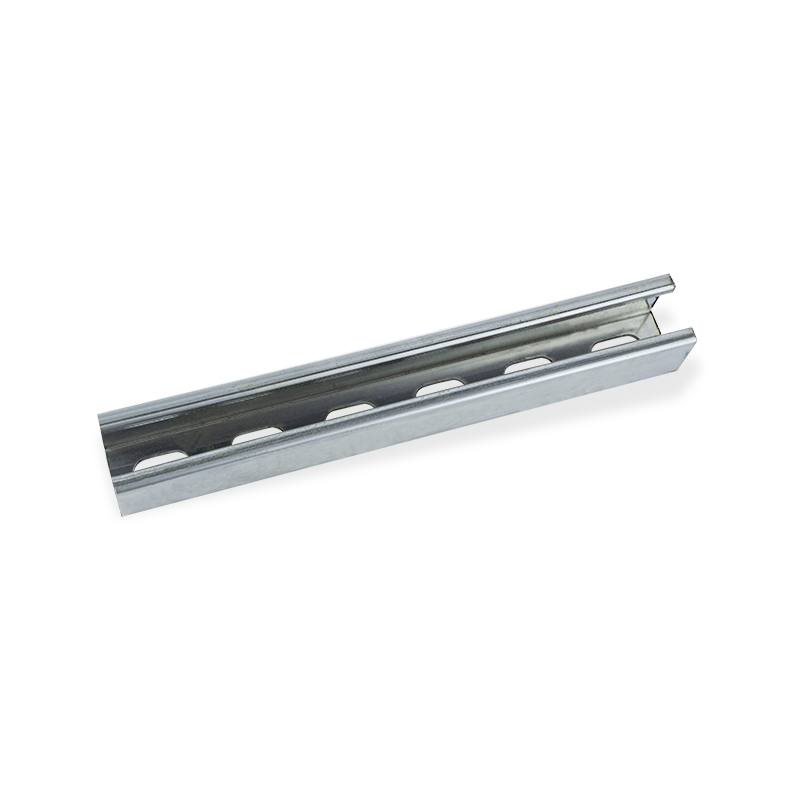
Slotted U channel wire duct cable tray
Structural Mechanics & Material Engineering Considerations
Cross-Sectional Geometry & Load Behavior
The core strength of the U-Channel lies in its cross-sectional geometry. Structural stiffness is proportional to the moment of inertia, and deeper side walls significantly enhance the moment of inertia.
Load & Deflection Control
- A deeper side wall increases the moment of inertia, which minimizes mid-span deflection ($\delta$) under load.
- This reinforcement is crucial for long support spans (exceeding 1.5–2.0 meters) and when carrying heavier power lines.
Material Composition & Finishes (Corrosion Resistance)
Selecting the correct material is crucial for long-term reliability and corrosion resistance:
- Hot-dip galvanized steel: Offers superior corrosion resistance for semi-outdoor or moderately corrosive industrial spaces.
- Stainless steel (304/316): Essential for chemical-heavy, food processing, or coastal environments (high chloride levels).
- Aluminum: Chosen for lightweight installations and excellent strength-to-weight ratio.
- Powder-coated finishes: Used to enhance aesthetics and offer additional protection against humidity.
Thermal Management & Ventilation Optimization
Effective heat dissipation is a design priority to prevent cable insulation aging and system failure.
Heat Dissipation Path Analysis
Because U-Channel Trays are semi-enclosed, airflow is restricted, affecting convection.
- Perforated U channels are highly recommended to maximize convective cooling by increasing the surface area for heat exchange.
Ampacity De-rating
Heat buildup within the tray (the "oven effect") necessitates reducing the maximum allowable current (ampacity) for the cables.
- Engineers must apply an ampacity de-rating factor (typically $0.7$ to $0.85$) based on cable fill and ambient temperature.
- Failure to de-rate leads to excessive $I^2R$ heating and compromises long-term cable reliability.
Cable Fill Ratio, Segregation Rules & Pathway Optimization
Fill Ratio Engineering
The Cable Fill Ratio (CFR) dictates the available space within the tray, directly impacting thermal management and accessibility.
- The recommended CFR for U channel trays is generally 40–50% of the available cross-sectional area.
- A lower ratio ensures adequate heat dissipation and provides necessary space for future expansion.
Signal Integrity & Interference Avoidance
Proper segregation is necessary to prevent Electromagnetic Interference (EMI) and ensure signal integrity.
- Divider plates (vertical barriers) must be used to maintain necessary horizontal separation between sensitive communication cables and high-power conductors.
- Isolate high-frequency or high-power cables from sensitive instrumentation or data lines.
Optimizing Cable Run Paths
Efficient routing minimizes cable stress and simplifies installation.
- Minimize sharp turns or unnecessary direction changes.
- Use smooth radius fittings (bends, elbows) for all transitions to prevent cable strain and damage to insulation.
Mechanical Support Design & Span Engineering
Support Spacing Parameters
Support spacing is determined by the calculated load and the material strength of the tray.
- Typical spacing ranges from 1.2 to 3.0 meters.
- Longer spans or environments with significant vibration exposure will necessitate closer spacing or reinforced tray profiles.
Load Calculations Beyond Cable Weight
Robust design uses safety factors to account for all potential loads.
- Static Load: Cable weight, tray weight, and anticipated dust accumulation.
- Dynamic Load: Temporary weight from installation crews or maintenance personnel.
- Environmental Load: Forces from seismic activity or persistent vibration.
- A Safety Factor (SF) of $1.5$ to $2.0$ is mandatory to guarantee system reliability.
Accessory Engineering: Fittings, Joint Stability & Modularity
Elbows, Tees & Transitions
- Use smooth-radius fittings to prevent sharp kinking or crushing of cables.
- Employ vibration-resistant clamps for secure, stable connections.
Joint Reinforcement
Joints are the weakest points in the system and must be reinforced.
- Use thicker-gauge steel connector plates for heavy-load installations.
- Strictly adhere to manufacturer torque specifications when tightening bolts.
Grounding & Bonding
Proper grounding and bonding are safety and electrical necessities for fault current suppression and noise control.
- Install bonding jumpers between adjacent tray sections.
- All grounding points must be clearly labeled and readily accessible for inspection.
Installation Workflow & Engineering Best Practices
Pre-Installation Verification
Thorough planning prevents costly on-site rework.
- Confirm the load-bearing capacity of the structure (walls, ceilings).
- Identify and resolve potential routing conflicts with other building systems.
- Assess maintenance accessibility for future cleaning and inspection *before* installation.
On-Site Alignment & Leveling
Using a laser level for precise alignment is crucial to reduce cable stress and enhance system stability.

Inspection & Long-Term Maintenance
A formal maintenance plan extends service life and ensures safety.
- Annual torque checks on all brackets and connectors.
- Periodic cleaning to remove dust and debris that can impede thermal performance.
- Thermal scanning can be used to non-invasively detect hotspots in power cable bundles.
Selecting the Right U-Channel Cable Tray: Engineering Checklist
| Design Factor | Key Engineering Consideration |
|---|---|
| Load Rating | Evaluate maximum expected load + SF of 1.5–2.0. |
| Environment | Select material (Galvanized, Stainless, Aluminum) based on corrosion and chemical exposure. |
| Thermal Mgmt | Mandate perforated base and apply ampacity de-rating factor ($0.7–0.85$). |
| Fill Ratio | Maintain 40–50% CFR for thermal and expansion space. |
| Separation | Specify divider plates to isolate sensitive and power cables. |
| Safety | Confirm all sections are grounded and bonded with low-impedance jumpers. |


Youming Group is a manufacturing group company mainly engaged in the research and development of new high-strength cable tray
Product
- Wire Type Cable Tray Series
- Punched Type Cable Tray Series
- Trough Type Cable Tray Series
- Cable Rack Ladder Series
- Ladder Type Cable Tray Series
- Marine Cable Ladder Tray
- Strut Channel Cable Tray Series
- Accessories
- Fiber Cable Tray/Optic Cable Tray
- Photovoltaic Stents
- Stainless Steel Cable Tray Series
- Aluminum Alloy Cable Tray System
Contact information
-
No.36, Taidong Industrial Zone Shiyan Town, Dongtai City, Jiangsu Province
