 English
 русский
 Español
 Português
 Deutsch
 عربى
عربى italiano
 Türk
Türk हिंदी
हिंदी Indonesia
 Tiếng Việt
If you need any help, please feel free to contact us
Evaluating Load Capacity and Safety Factors of Trough Cable Tray Systems
Content
For large-scale infrastructure, power, and industrial projects, the stability of the cable management system is non-negotiable. The **Trough Cable Tray** is widely chosen for its full containment design, which protects sensitive cables from dust and external elements. However, project safety relies heavily on a meticulous engineering assessment of the tray's structural limits. B2B procurement must demand compliance with **Trough cable tray load testing** standards and verify the calculated **Maximum span for trough cable tray** based on the actual load. Jiangsu Youming Group Co., Ltd., a specialized, innovative high-tech enterprise in cable tray manufacturing, provides verified products across stainless steel, aluminum alloy, and galvanized series, supported by our in-house testing center and advanced automated production lines.
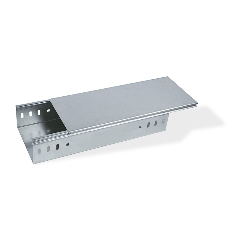
Galvabized steel cable trunking tray with cover
Interpreting Load Capacity and Testing Standards
Safety in cable management is a function of tested limits and established safety factors.
Understanding Trough cable tray load testing standards
Load capacity must be verified through controlled **Trough cable tray load testing** procedures, typically following industry specifications such as NEMA VE 1. These tests subject the tray system to calculated loads over a specific span until failure. The published safe working load is derived by dividing the ultimate failure load by a prescribed safety factor (often 1.5). This ensures that the installed system has a substantial buffer against unexpected increases in weight or environmental stress. Procurement should always request copies of these certified test reports.
The interplay of Load vs. Maximum span for trough cable tray
The relationship between the applied uniformly distributed load (UDL) and the **Maximum span for trough cable tray** is inverse and depends critically on the tray's cross-sectional dimensions and the thickness (gauge) of the metal. A wider tray or a thinner gauge will necessitate a shorter **Maximum span for trough cable tray** for the same load, or conversely, a heavier gauge will allow a longer span. Failure to respect these manufacturer-specified charts based on **Trough cable tray load testing** results can lead to permanent deformation or structural collapse.
Comparison: Tray Gauge Thickness vs. Maximum Span and Load Rating (Example Data):
| Tray Gauge (Thickness) | Maximum Span (for 400 N/m UDL) | Relative Load Rating |
|---|---|---|
| 1.5 mm | 2.0 meters | Medium |
| 2.0 mm | 3.0 meters | High |
Deflection Control and System Integrity
Beyond structural failure, controlling movement is essential for cable longevity and system alignment.
Managing Trough cable tray deflection limits
While load capacity addresses catastrophic failure, **Trough cable tray deflection** limits address functional integrity. Excessive vertical sag not only appears unprofessional but can impose undue stress on the cables themselves, potentially damaging fiber optics or causing insulation degradation over decades of service. Industry best practice often restricts **Trough cable tray deflection** to the span length divided by 240 (L/240). Achieving this low deflection requires careful adherence to the **Maximum span for trough cable tray** charts provided by the manufacturer.
The impact of Cable fill ratio for trough tray installation on load
Engineers must accurately determine the total weight on the tray, factoring in the **Cable fill ratio for trough tray installation**. The *fill ratio* (the percentage of the tray's cross-sectional area occupied by cables) is critical for determining thermal performance, but the *actual cable weight* determines the structural load. Overlooking potential future capacity needs, or inaccurately estimating the density of various power and communication cables, can lead to under-specification of the **Trough Cable Tray** and premature failure.
Material and Manufacturing Factors
Material choice and production consistency are guarantees of long-term performance.
Technical advantages of Stainless steel trough cable tray specifications
For environments subject to high humidity, corrosive chemicals (e.g., pharmaceutical, petrochemical), or extreme temperatures, galvanized steel is insufficient. **Stainless steel trough cable tray** specifications (typically using 304 or 316 grades) offer superior corrosion resistance and increased yield strength. While the initial cost is higher, the extended service life and reduction in maintenance costs make **Stainless steel trough cable tray** systems the most economical long-term choice in these demanding sectors.
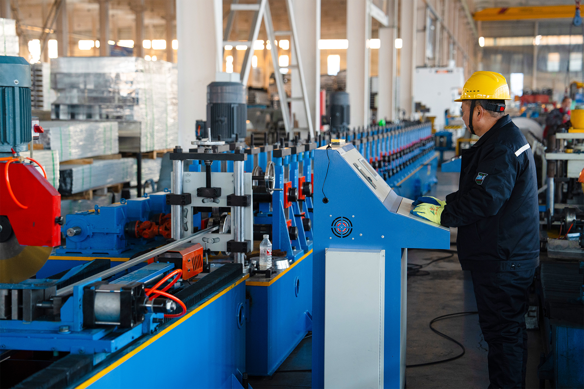
Manufacturing precision and structural reliability
The accuracy of the tray's form—its width, depth, and flange integrity—is crucial. Jiangsu Youming Group's fully automatic production lines, including laser cutting and CNC punching, ensure that the tray's geometry is consistent across every segment. This precision is vital because the load-bearing calculations and **Trough cable tray load testing** results are based on exact, verified cross-sectional properties. Any deviation in the manufacturing process can compromise the calculated **Maximum span for trough cable tray**.
Conclusion
The procurement and installation of **Trough Cable Tray** systems demand an engineer-level focus on structural integrity. Project success requires diligently comparing the **Maximum span for trough cable tray** against the projected load, respecting strict **Trough cable tray deflection** limits, and ensuring the **Cable fill ratio for trough tray installation** accurately reflects the total weight. Whether choosing standard galvanized or specialized **Stainless steel trough cable tray** materials, reliance on products verified by stringent **Trough cable tray load testing** is essential. Jiangsu Youming Group Co., Ltd., with its certified production processes and testing center, is the high-quality partner for providing reliable cable tray solutions to the world's most demanding projects.
Frequently Asked Questions (FAQ)
- What is the typical safety factor used in **Trough cable tray load testing**? Industry standards generally mandate a minimum safety factor of 1.5. This means the ultimate failure load of the **Trough Cable Tray** must be at least 1.5 times greater than the published safe working load.
- How does **Cable fill ratio for trough tray installation** impact the tray's cooling performance? Although the fill ratio does not directly affect the tray's structural **Trough cable tray load testing** capacity, a high fill ratio (e.g., above 40%) restricts air circulation, leading to thermal buildup and the need to derate the ampacity of the contained power cables.
- What is the primary technical benefit of using a **Stainless steel trough cable tray** over hot-dip galvanized steel? The primary benefit is vastly superior long-term corrosion resistance. Hot-dip galvanized coating degrades over time, especially in acidic or coastal environments, whereas the passive oxide layer on **Stainless steel trough cable tray** provides continuous, superior protection.
- Can the **Maximum span for trough cable tray** be increased by reinforcing the bottom? Yes. Manufacturers can often increase the **Maximum span for trough cable tray** by incorporating longitudinal stiffeners or heavy-duty flanges, effectively increasing the cross-sectional moment of inertia, which is the primary structural property governing span and **Trough cable tray deflection**.
- How does a project manager verify the **Trough cable tray deflection** claim? The project manager should request the manufacturer's load tables, which typically list the calculated deflection at the midpoint of the span for the stated load. This deflection should be confirmed against the project's specified limit (e.g., L/240).


Youming Group is a manufacturing group company mainly engaged in the research and development of new high-strength cable tray
Product
- Wire Type Cable Tray Series
- Punched Type Cable Tray Series
- Trough Type Cable Tray Series
- Cable Rack Ladder Series
- Ladder Type Cable Tray Series
- Marine Cable Ladder Tray
- Strut Channel Cable Tray Series
- Accessories
- Fiber Cable Tray/Optic Cable Tray
- Photovoltaic Stents
- Stainless Steel Cable Tray Series
- Aluminum Alloy Cable Tray System
Contact information
-
No.36, Taidong Industrial Zone Shiyan Town, Dongtai City, Jiangsu Province
